Pages

Thursday, June 6, 2019

1963/4 RCA Victor Stereo Console Model 4 VF 289 restoration

New Project to steal away what little time I have!

1963/4 RCA Victor Stereo Console   Model 4 VF 289
Acquired at an antique store/estate sale in Lake land for $30


Goals
1. Restoration
     - Tube Amplifier
     - RCA Studomatic RP218 Turn Table
     - FM/AM Radio
     - The Cabinet


 After clean up (dusting, disinfecting and de-roaching,...lol)


OK, let's take a look at the tube amplifier


I will need to replace all those 50+ year old capacitors before I attempted to plug this thing in! I downloaded the schematic from radiomuseum.org   and order a bunch of replacement capacitors 


Bad  Caps!  

New Caps in place!


DIY  jack  to test Amp with Ipod


Sunday, July 7, 2013

Robot Building

Finally all the pieces are in place and I took the robot for a wireless ride around the house. The original VSI controller have been officially hacked.  The robot still retains all the functionality of the original VSI and also can be switch to Radio Control at the drop of a hat!
I needed to build a low pass filter for the PWM output from the arduino  and it worked out pretty well.
The fillers smooth out the PWM pulses as explained in this article
http://arduino-info.wikispaces.com/Arduino-PWM-Frequency


There is a noticeable delay when I move the stick on the RC transmitter, kinda  frightening when the see the robot takes off and does not respond to the stop command immediately!
I will play around with different values of resistors and capacitors in the coming weeks to increase the responsiveness.


I also had to re-write the code for the arduino that I posted some time ago, pretty simple indeed but It will get very much more complex when I  add bump, and ultrasonic sensors. These will be autonomic sensors to prevent the robot from bumping into things and falling off edges. etc. Ideally a visual sensor system  would be the navigation system of choice to prevent bumping  into thing and falling off steps and overhangs.


Next  on the list of  things to be done
1. I will tidy thing up a bit by using a arduino shield for the filters and a project box to host all the electronics.
2. Add support to the code for the horn and speed selector ( why do I need the horn working?)
3. Add bump sensors and supporting code
3. Add ultrasonic sensors and supporting code


Monday, February 4, 2013

Robot building

Wow! could not have imagine that 4 years has past since I started this project. Actually, I had started it with the hopes that one of my three sons would have jumped in and completed it. tsk...tsk...oh well here we go. Just to summarize: In 2009 I acquired a broken electric wheelchair to be used as a base for robotic projects. I stripped it down got it working and planned to tap into the factory controller. Today, I hacked the controller, extended the internal ribbon cabling with additional FCI 6 pin Headers and a 8 way rotary switch. Here is the initial plan
The Splice
From the controller's documentation they are 2 wires that control the forward and reverse motion and two that controls the left and right steering. Other wires are ground, 2.5 v reference voltage and 5 volts power. Time to check is the hack to see if the controller works, and it did! with a little bit of fiddling. (I did not pay much attention to the way the FCI connectors were originally oriented.) The FCI Headers were source from http://www.mouser.com/ part number 89361-708LF The rotary switch is a generic one from ebay. The rotary switch is to be used for switching the forward/reverse & left/right input between other signal sources, for example RC receiver/ARDUPILOT or on board computer.

Sunday, July 18, 2010

Recycled Volvo Amps provide 130 watts of sonic power for the desktop


A couple weeks ago I was cleaning my garage and came across these Volvo amplifiers from my 86 Volvo 760 (wonderful car worth every penny!) I was about to trash them but I decided to build a portable desktop power amplifier.
The smaller amplifier is HA-3121 and rated at 25 Watts per channel, the rear amplifier HA-3141 is rated 40 watts per channel. Ok, a 130 watts desktop power amplifier!
Since I was in the recycling mood I salvage an assortment of RCA inputs, speaker connectors, switches, LEDs, from my garage cleanup. I also used rails and nuts and bolts left over from my flat panel TV mount.


I temporarily hook up all the wires to a 12 volt wall transformer and was disappointed that nothing works (very low current). I then quickly connect a 12 automotive battery and only the HA-3141 came alive, the HA-3121 did not. The problem was traced to a faulty relay, probably the reason the amps were out of the car in the first place. A few taps on the relay and a few minutes of activating deactivating it and now the relay works trouble free.


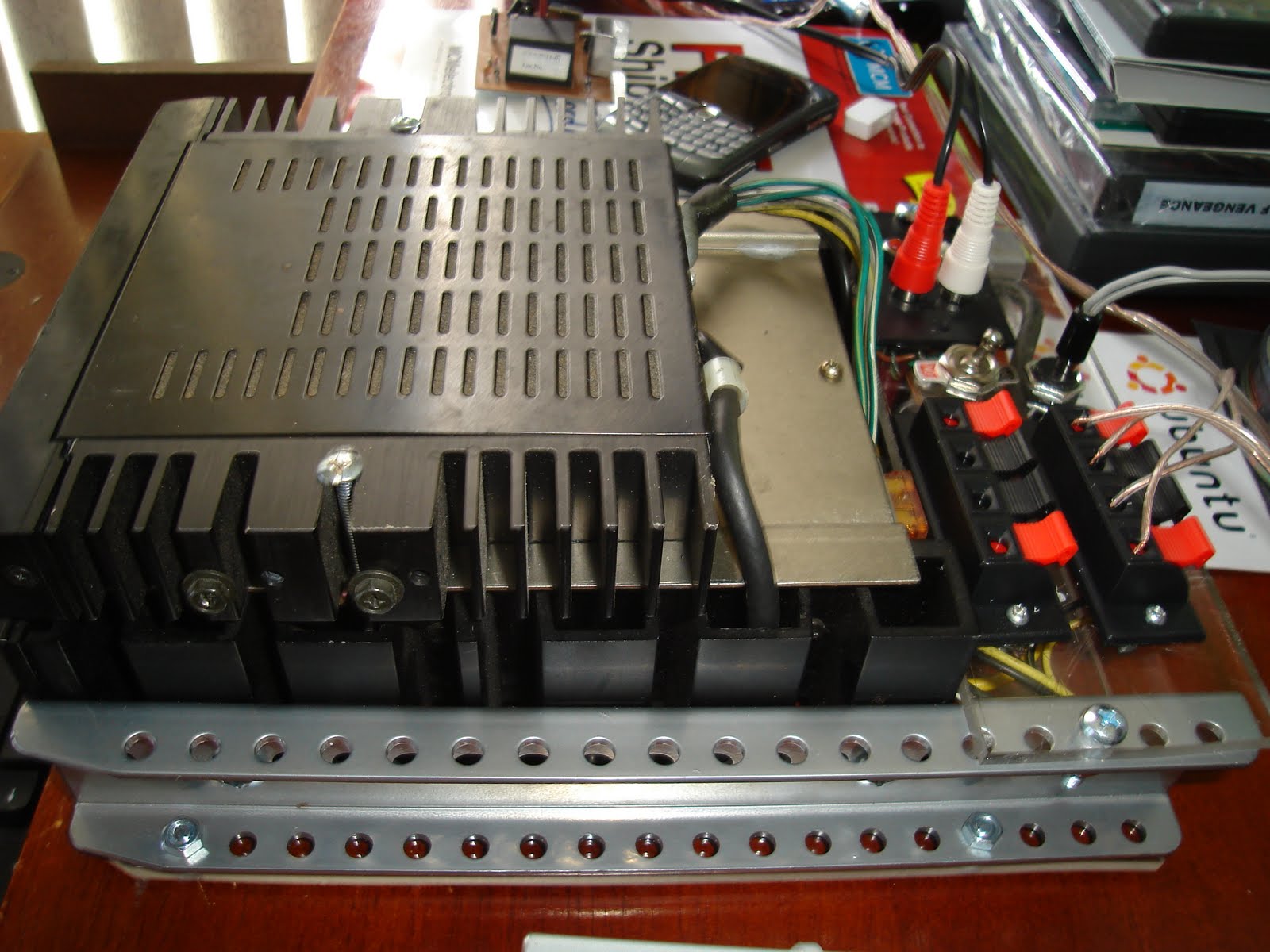
Bolted the rails to the main power amp.


Bolted the secondary amp to the main amp. The main amp had a mounting plate allows for a 1/4 inch air gap.


A piece of Plexiglas foundation for the input, power and output connectors.


The 12 automotive battery provided plenty clean current which the wall transformer could not. I hooked up my bench top power supply recycled from a computer power supply. The plans are here http://www.wikihow.com/Convert-a-Computer-ATX-Power-Supply-to-a-Lab-Power-Supply
*** Of course be very careful when working with electricity, line voltage can and will kill! ***
The computer power supply yields approximately 11.7 volts plenty of oomph as I take the amplifier to max. There is a limited amount of voltage available in an automobile (approximately 13.5 volts). This means that the amplifiers have fewer than 12 volts to apply to the speaker leads after factoring internal system resistance. If we have only 12 volts to drive into a speaker, there may not be sufficient volume output if the speaker has high impedance; therefore I wire my 8 ohms speakers in parallel for 4 ohms to maximize the output power to the speakers. (Ohm’s law)


Wiring for the HA-3121
Speaker wires

left output: green/yellow -
left output: green/white +

Right output: gray/yellow -
Right output: gray/white +

Power
Yellow constant 12 Volt
Black (thick) Negative ground
black (small) not connected

Input (shielded bundle)
Orange 12 volt remote on

left input: Blue (contains 2 wire, unshielded is negative)

Right Input: Green (contains 2 wire, unshielded is negative)

Ignore all other wires ( red, black etc)

---------------------------------------------------------------------

Wiring for the HA-3141
Speaker wires

left output: Black -
left output: Yellow +

Right output: black -
Right output: white +

Power
Yellow constant 12 Volt
Black (thick) Negative ground
black (small) not connected

Input (shielded bundle)
Orange 12 volt remote on

left input: Blue (contains 2 wires, unshielded is negative)

Right Input: Green (contains 2 wires, unshielded is negative)


Ignore all other wires ( red, black etc)


free counters

Sunday, November 22, 2009

Arduino, Vex receiver and signal splitter


The Setup : The Arduino powers the vex decoder via 5v which in turn powers the vex receiver, no other external power required.

5 volts is sent from the arduino to the signal splitter via the positive output of one the the channel connection. The signal splitter ground connection is connected to the arduino ground.
The 5 volts also flows through the "receiver - splitter" connection.

Vex Properties via the signal splitter
Channel 1,2,3 & 4
range : from 753 to 2241
Center stick position varies between 1480 and 1510


Channel 5 & 6 (digital Channels)
range : off = 753 on = 2241

arduino Code


/*
nikitanicholas@gmail.com
Use freely

Vex transmitter & Vex receiver kit : http://www.vexrobotics.com/vex-robotics-transmitter-receiver-add-on-kit.shtml
Vex signal splitter : http://www.vexrobotics.com/vex-robotics-signal-splitter.shtml

Vex Properties via the signal splitter
Channel 1,2,3 & 4
range : from 753 to 2241
Center stick position varies between 1480 and 1510

Channel 5 & 6 (digital Channels)
range : off = 753 on = 2241
not activated: 1500

The Setup
The Arduino powers the vex decoder via 5v which in turn powers the vex receiver, no other external power required.


*/
#define channelNumber 6 // 6 Channels on the vex

int value[channelNumber];
int val;
int adrinoPin;
void setup()
{
Serial.println("init");
Serial.begin(57600); //Serial Begin
pinMode(2, INPUT); //Pin 2 as input
pinMode(3, INPUT); //Pin 3 as input
pinMode(4, INPUT); //Pin 4 as input
pinMode(5, INPUT); //Pin 5 as input
pinMode(6, INPUT); //Pin 6 as input
pinMode(7, INPUT); //Pin 7 as input


}
void loop()
{
adrinoPin = 2; // start with pin 2
Serial.println("looping......");

for(int x=0; x<=channelNumber-1; x++)//Loop to print the channel readings
{
if (pulseIn(adrinoPin, HIGH) == 0 )
{
Serial.print("No signal on Channel" );
Serial.print(" ");
Serial.print(adrinoPin -1); //Print channel
Serial.println("");
}
else
{
Serial.print("Channel" );
Serial.print(" ");
Serial.print(adrinoPin -1); //Print out the channel number
Serial.print(" = ");
//val = .pulseIn(adrinoPin, HIGH);
val = normalizedPPM(pulseIn(adrinoPin, HIGH));
Serial.print(val); //Print out the value
Serial.print(" ");
}
value[x]=0; //Clear the array after printing
adrinoPin++; // increment pin count

/* Future Project
* Output PWM voltage based on Vex signal pulsein
* The pins marked PWM (pins 3, 5, 6, 9, 10, and 11) can be pulsed using the analogOut()
* Pulsewidth is a value from 0 - 255. 0 corresponds to 0 volts, and 255 corresponds to ~5 volts.
* Every change of one(1) point changes the pseudo-analog output voltage by 5/255, or 0.0196 volts.

When no signal is received from the Vex transmitter or when the transmitter stick prositions are centered
the following should occur : arduino output 50% duty cycle corresponding to approx. 2.5v ( PWM to output pin is 127)

When Pulsein is between 1550 and 2200
the following should occur : arduino output 75% duty cycle corresponding to approx. 3.5v (PWM to output pin is 178)

When Pulsein is between 750 and 1450
the following should occur : arduino output 25% duty cycle corresponding to approx. 1.5v (PWM to output pin is 76)

Available pins 9, 10 , 11
*/


}

Serial.println("");

delay(500);

}

/*
Smoothing out the center channel ( software trimming)
*/
int normalizedPPM(int ppm)
{
if ( ppm > 1480 && ppm < 1510)
return 1500;
else
return ppm;

}


Saturday, November 21, 2009

Robot building


In my earlier blogs I hinted on a robot built with a posting of
Arduino, Vex receiver and signal splitter.


Electric wheelchair inspection and breakdown


I picked up a broken electric wheelchair Jet3 Ultra from the local flea market for $50. It was complete with a broken chair support but not running. I began to strip it down to the bare essentials i.e. remove the seat and support, leg rest arms, fenders and bumpers. I replace the fuse and tinkered around with the controller and finally got it to power up. Here you have it! a complete, powered, really sturdy robot base that can really cut down on development time.


High Level design parameters


1. Keep original wheel chair controller: The controller have a number of built in safe guards such as locking the wheel when not active, power on test, speed control especially when turning at high speeds.

2. Incorporate a wireless control : Arduino, Vex receiver and signal splitter.

3. Computer control: Automation with various sensors such as digital compass, accelerometers, vision, maps, internet, LCD display and whatever I can throw at it.


The original motor controller


The key to success in interfacing with wheelchair motor controller is to tap into the joystick input.

First, we will need a switch to flip between joystick and an alternate source of input: computer and or remote control.


free counters